Optical Fiber
________________________________________
Follow us on Facebook
Follow us on Google+
________________________________________
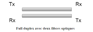
An optical fiber transmitting data in one direction only. Also for two entities communicate in full duplex, an optical cable must contain two optical fibers, one for transmission and one for reception. Cable can contain from 2 to 48 fibers. Fibers joined together in a cable does not create noise, because they do not carry electrical impulses that could induce electromagnetic interference. Therefore they do not need a protective shield, such as copper son.A fiber optic cable is supported with son plastic reinforcement, such as Kevlar. This makes a stronger cable, ensuring that optical fibers do not deteriorate when folded.
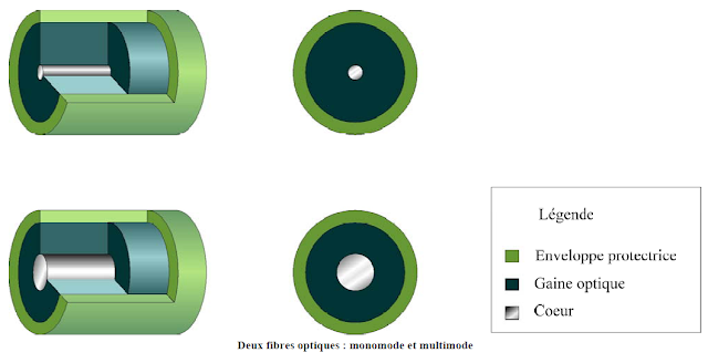
Light is guided in the center of the fiber, called heart. The heart is composed mainly of silicon dioxide (silica), enriched with other elements. It is surrounded by the cladding. The sheath is made of silica, but its refractive index is much lower than the heart. This allows to precisely reflect the light.
The cladding is protected by a jacket, made of plastic frequently.
The road is a ray is also called a mode. When optical fiber transmits a single ray, it is called single-mode fiber. Fiber that transmits several rays, it is called multimode fiber. For transmitting a plurality of spokes with different paths, the core of the multimode fiber to be greater than that of the single mode fiber.
Sources that scatter light in the fiber are not the same for singlemode and multimode fiber. Indeed, a multimode fiber uses LED (Light Emitting Diode), French "LED" Light Emitting Diode, while a single-mode fiber using the laser, which is generally more expensive. A laser emits rays of longer length than that of the rays emitted by an LED. Therefore, the maximum length of the multimode fiber is 2000 m. While the maximum length of the single mode fiber 3000 m. Single-mode fibers are more expensive and their use is frequently intended for WAN links between different buildings. Multimode fibers are cheaper and more used in business.
The fiber diameters have different sizes. In the diagram below you can see the types multimode and singlemode aligned, showing the relative sizes of different diameters.
Most of the equipment for local area networks transmit data in electrical form. In order to integrate the optical fiber in such a network, the electrical signals must be converted into light pulses. To do so, there are transmitters that convert, encode and send light signals. As already stated, there are two types of light source:
- LED: light emitting diode generates light infrared length of 850 nm or 1310 nm.
- LASER: (English: Light Amplification by Stimulated Emission Radiation) light amplification by stimulated emission of radiation produced narrow beams infrared light with high intensity and wavelength of 1310 nm or 1550 nm.
The fiber ends are attached to the connectors that plug into the sockets of transmitters and receivers. SC-type connectors (Subscriber Connect) are most often used for multimode fibers and connectors type ST (Straight Tip) most frequently used for singlemode fiber. The diagram below shows the ST and SC, respectively.
A pair of connectors attached in a nest is called a duplex connector. A simplex connector is a simple connector that connects a fiber only.
Optical cables that exceed the maximum length is extended by repeater equipment for amplifying light signals.
Signals and noise in optical fibers
Despite the fact that the optical fiber is the best transmission media, signals passing through them can be mitigated by several factors. The most important factor is the decrease in signal caused by dispersion. It happens when the fiber is bent or too tight. The incident angle of a ray may then be less than the critical angle and a portion forming the beam is refracted. Absorption is another form of mitigation. It happens when a ray encounters impurities on its way.
To counter the problems of attenuation, we test the fiber optic links with tools that measure the energy loss and the travel time of the signals.


