How to Configure Windows Network WiFi :


Configure Windows Network WiFi :

 ________________________________________

Follow us on Facebook

Follow us on Google+

________________________________________

WiFi configuration is a daily need for internet users in this article we will assist you step by step to configure  Windows 


Set up a wireless network in Windows :


Windows , connecting to a wireless network is normally no problem. Windows  detects the wireless network and displays the list of available networks, and then to the installation, we have already informed the type of network, home network, also called home network.


Windows includes a wireless network manager that we will use to set the configuration.


Go to the << Start >> menu and click  << Connexion >>

 
 << Connect to a network >> window opens.


From this window, you must right-click on << Wireless Network Connection >> (Connexion réseau sans fil )


Click << Connect / Disconnect >>


"Connect to a network" opens


  •  One or more networks are listed, and you must select one for your box. A Neufbox will identifier (SSID) Neuf_xxx a Orange Livebox-xxx-xxx one AliceBox Alice, etc ... Once your choosing, click  << Connexion >>
  • You then need to enter the encryption key of your modem or your Box (Key WEP / WPA). Look at the back of your modem or your Box to find the network key (Note that if you have an AOL Box, network key is "WEP" on the label). Check if the option << Show Characters >> to display the key that was entered (this facilitates the entry), and then click "Connect". Note that the key is in the form of numbers and letters, if the presentation is separated: then do not enter.


Wait a few moments for the connection is established :

 
When the connection is established, a window offers you to save settings for the wireless network. Check both << Save this network >> and << Start this connection automatically >> to connect automatically each time you start Windows  Click  << Close >>. 


When the connection is established for the first time, it is necessary to specify the type of connection: home, office, public place. Depending on your choice, Windows will set different sharing settings.


Takes place an icon in the bottom right of the screen and informs you of the status of the network connection.


The connection is established and the WLAN icon appears without the yellow star. The wireless network is functional.


Normally, the connection is established and you can connect with your browser.

Note:  some box in addition criptage activate WEP key authentication Mac. For the box and consider authorizing the use of internet, the PC must be WiFi identified. For this, the box Livebox, or Neufbox Dartybox have a button combination on which we must rely for any PC in the immediate environment of the modem is associated and authorized. The modem Alicebox the Mac key is not enabled by default, however if this is the case I suggest you log in and go to ethernet modem interface is to disable or seize key MAC PC.
 

Installing VPN server on Windows 2003

  Installing VPN server on Windows 2003

 ________________________________________

Follow us on Facebook

Follow us on Google+

________________________________________


Presentation

A virtual private network (VPN) is a way to connect to a private network through a public network is the Internet. It combines the advantages of remote connection with a remote access server with the ease and convenience of Internet connection

The solution to install a VPN server in Tissea SARL allow the remote sites can access the network seamlessly and securely. Therefore, it was necessary to link these sites together so they can share resources and materials to increase their productivity.

Communication between sites

Before the emergence of the company VPN to connect these multiple physical networks, it y'avait one
dedicated line that carried a WAN between these networks for a while. The main purpose of the VPN
was to allow a remote machine to a network (eg Marrakech) to access by
the Internet, and all ensuring security of data exchanged. This is
established, once connected to the Internet, the user can create a VPN between your machine and the remote network.
Here is a concrete illustration picture:


Components of a VPN server

explanations

In Windows 2003, the protocol virtual private network consists of the following components:

1 VPN server, 1 (n) client (s) VPN, 1 VPN connection (this is the part of the connection in which the data are encrypted) and the tunnel (the portion of the connection in which the data is encapsulated).

Tunneling is done through one of the tunneling protocols included with Windows 2003
(existing in 2000), which are both installed with Routing and Remote Access, or
service called "RRAS" (Routing and Remote Access). The two major tunneling protocols
included with Windows 2003 are:

- PPTP (Point-to-Point Tunneling Protocol), which provides data encryption using the Point to Point Encryption Microsoft Corporation.


- L2TP (Layer Two Tunneling Protocol) that provides encryption, authentication, and integrity
data using IPSec.
Note, however it is recommended that your Internet connection uses a dedicated line
T (n) or fractional frame relay. The WAN adapter must be configured with the IP address and
subnet mask assigned to your domain or supplied by a provider, as well as the gateway
default ISP router.

Differences between PPTP and L2TP/IPSec

We have seen that Windows 2003 supports two VPN protocols that are:
- PPTP (point to point tunneling protocol)
- L2TP (Layer 2 Tunneling Protocol).
PPTP uses MPPE encryption method (Microsoft Point to Point Encryption) while
L2TP is based on IPSec. However, for encrypted communication with PPTP
it is necessary to have used the following methods of authentication:
- MS-CHAP v1 or v2
- EAP / TLS for smart cards.
(IPSec requires no particular authentication method)


The method MPPE to encrypt on 40.56 and 128-bit to use the 128-bit encryption it was necessary to have installed the High encryption pack (included in the service pack3) and install a patch for versions correction Windows 95 and 98 but with Windows 2003 it is resolved.
Here is a table of the main features of PPTP and L2TP


Installation on Windows 2003 Server

Installation and activation of vpn


To install and activate a VPN server on Windows 2003 server, follow these steps:
1) Firstly, the VPN unit with Microsoft Windows 2003, confirm that the connection to the Internet and connect to your local area network (LAN) are both configured correctly, this is important for the next steps :
2) Click Start, point to Administrative Tools, and then click Routing and Remote Access.


3) Click on the server name in the tree, and then click Configure and Enable Routing and Remote Access on the Action menu. Click Next.


4) In the Common Configurations dialog box, click Virtual Private Network (VPN server)
then click Next.


5) In the Protocols dialog box remote client, confirm that TCP / IP is included in the list;
click Yes, all protocols are available in the list, then click Next.
6) In the Internet Connection dialog box, select the Internet connection you used to
connect to the Internet, then click Next.
7) In the dialog box, IP address assignment, select Automatically to use the
DHCP server on your subnet to assign IP addresses to remote access clients and
server.
8) In the dialog box Managing multiple remote access servers, confirm that the check
select No, I do not want to configure this server to use RADIUS now activated.


9) Click Next, then click Finish.
10) Click the right mouse button on the node Ports, and then click Properties.
11) In the Properties dialog box of ports, click the device WAN Miniport (PPTP), and then click Configure.
12) In the dialog Configure Device - WAN Miniport (PPTP), this possibility is offered to you:
NB: If you do not want to support a VPN user dialup modems direct
installed on the server, clear the checkbox dial routing connections on demand (inbound and outbound).
13) Enter the maximum number of simultaneous PPTP connections you want to allow in the area
text Maximum ports. (This number may depend on the number of available IP addresses.)
14) Repeat steps 11 through 13 for the L2TP device, and then click OK.

VPN server configuration


Configuring the remote access server as a router
For our remote access server to forward traffic correctly on your network, you
must configure it as a router with either static routes or routing protocols,
so that all sites on the intranet are reachable from the same remote access server.
To configure the server as a router:
1) First, click Start, point to Administrative Tools, and then click Routing and
Remote Access.
2) Right-click on the server name, and then click Properties.

3) On the General tab, select Enable this computer as a router.
4) Select Routing for LAN routing only or LAN and dial
demand. Finally click on "OK" to close the Properties dialog box.
Configuring PPTP ports

Confirm the number of PPTP ports you need. To check the number of ports or add ports, follow these steps:

1) Click Start, point to Administrative Tools, and then click Routing and Remote Access.
2) In the console tree, expand Routing and Remote Access, expand the name of
server, and then click Ports.
3) Click with the right-click Ports, and then click Properties.
4) In the Properties dialog box of ports, click Port Mini WAN (PPTP), and then click Configure.
5) In the dialog Configure Device, select the maximum number of ports
the device, and then select the options to specify whether the device accepts
incoming connections only or both incoming and outgoing connections.

How to allow a user to connect to a VPN server installed on a Windows 2003 Server platform?

1 - Click on Start \ Administrative Tools \ Users and Computers or
Run: dsa.msc
2 - Select the desired user, display the context menu with the right mouse button, select
Properties.


3 - In the Dial-in tab, check the Allow Access.


The user is able to connect to the VPN.

Managing addresses and name servers


The VPN server must have IP addresses available, it must indeed assign to the virtual interface
VPN server and VPN client during IPCP negotiation phase (IP Control Protocol)
connection process. The IP address assigned to the VPN client is assigned to the virtual interface of the client
VPN.
For Windows 2003 VPN server, the IP addresses assigned to VPN clients are obtained by
Addressing DHCP by default. You can also configure a group of static IP addresses. the
VPN server must also be configured with name resolution servers (usually
addresses of DNS and WINS servers) to assign to the VPN client during the IPCP negotiation.
 

Vpn connection from a client 2000/XP

Creation of client connection

In the network connection settings, click Create a new connection:


Then click Next on the appearance of the window.
Then you will be asked to choose the type of connection:


Then, after clicking Next, choose VPN connection:


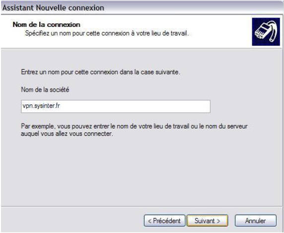
After validate this choice, enter the name of the company:


Then enter the address or name of the VPN:


Click Next, and then confirm the creation of the connection can be made a shortcut on the desktop for users "delta" can connect easily.

Client Connection Configured


Click the shortcut to clean the connection, enter your user name and the password and not the area provided by your network administrator and click "connect"


You now have in your corporate network:


conclusion


For a business, choosing to set up a VPN for remote sites and positions can be very
useful.

Indeed a low cost per reports the assets it can bring the VPN itself as a
complete and reliable solution to connect remote networks between them. Nowadays, performance and
the capacity of Internet access whether for domestic or professional help
use this technology without constraints.

For the customer, the usage is very simple and the user can work from home while recording their data on the server of its usual business for example and those responsible for the installation, except for updates configuration, there's little maintenance.

VPNs are inexpensive solutions compared to the price of leased lines and
allowing secure access to a corporate network.

Secure Access And Passwords


Secure Access And Passwords :


 ________________________________________

Follow us on Facebook

Follow us on Google+

________________________________________


Disable the reset passwords :

In some cases, it may be necessary to disable the service that allows you to reset the password on a router. It is important to note here that this deactivation can have serious consequences, for example, the obligation to return to the default configuration base (factory) router.

R1(config)# no service passwords-recovery

In case of loss of password, it will be impossible to reset the password of the super user. This command is part of the hidden commands Cisco IOS. I suggest you use it only if you do not have sufficient security level control physical access to your router. 

Set the minimum length of a password :


R1(config)# security passwords min-length 10

The router does not accept passwords less than 10 characters.


Limit the number of failed login attempts :

To prevent dictionary attacks and brute force passwords, limit the number of unsuccessful login attempts on your router (in our example, this number is 4).

R1(config)# security authentication failure rate 4 log

After four unsuccessful login attempts within one minute, the information will be recorded in the event log. 

R1(config)# login block-for 60 attempts 4 within 10

After four unsuccessful login attempts within an interval of 10 seconds, another attempt will be possible after 60 seconds, because the router will remain silent during this period.

During this period, it will be impossible to connect to the router. Which could affect administrators router with rights. To avoid this, it will create an ACL that allows administrators to log in during this period of silence (quiet-mode).
 

R1(config)# ip access-list standard login-permit-adm
R1(config-std-nac)# permit 172.16.20.0 0.0.0.255
R1(config)# exit
R1(config)# login quiet-mode access-class login-permit-adm


Prevent logins on lines (auxiliary, and virtual) :


/ / Auxiliary Line :


R1(config)# line aux 0
R1(config-line)# no password
R1(config-line)# login
R1(config-line)# exit


/ / Virtual lines :

R1(config)# line vty 0 4
R1(config-line)# no password
R1(config-line)# login
R1(config-line)# exit 


Just allow remote access via SSH (and telnet is not secure) :


R1(config)# line vty 0 4
R1(config-line)# no transport input
R1(config-line)# transport input ssh
R1(config-line)# exit


Configuring additional security for the VTY lines, console and AUX :


R1(config)# line vty 0 4
R1(config-line)# exec-timeout 5
R1(config-line)# exit

R1(config)# line console 0
R1(config-line)# exec-timeout 5
R1(config-line)# exit

R1(config)# line aux 0
R1(config-line)# exec-timeout 5
R1(config-line)# exit

R1(config)# service tcp-keepalives-in

Configuring SSH Security :


R1(config)# hostname Ottawa                                  // definition of hostname)
Ottawa(config)# ip domain-name cisco.com          // definition of the domain name)
Ottawa(config)# crypto key generate rsa                // generation of asymmetric keys
Ottawa(config)# username emabo secret cisco123

Ottawa(config)# line vty 0 4

Ottawa(config-line)# transport input ssh            // authentication configuration local and VTY
Ottawa(config-line)# login local
Ottawa(config)# ip ssh time-out 10                        // configure ssh timeouts
Ottawa(config)# ip ssh authentication-retries 3    // configuration time test new ssh


Pay special attention to vulnerabilities SNMP, NTP and DNS :


To ensure functionality, a router relies on other services such as  service name resolution. It turns out that these services are often vulnerable. it should therefore ensure that the ancillary services relied on a router are properly configure and secure.


Disable all services, protocols and unnecessary accounts :


R1(config)# no service finger                            // example of the finger service
R1(config)# no cdp run                                       // example CDP

Optical Fiber


Optical Fiber

 ________________________________________

Follow us on Facebook

Follow us on Google+

________________________________________

An optical fiber transmitting data in one direction only. Also for two entities communicate in full duplex, an optical cable must contain two optical fibers, one for transmission and one for reception. Cable can contain from 2 to 48 fibers. Fibers joined together in a cable does not create noise, because they do not carry electrical impulses that could induce electromagnetic interference. Therefore they do not need a protective shield, such as copper son.


A fiber optic cable is supported with son plastic reinforcement, such as Kevlar. This makes a stronger cable, ensuring that optical fibers do not deteriorate when folded.

Light is guided in the center of the fiber, called heart. The heart is composed mainly of silicon dioxide (silica), enriched with other elements. It is surrounded by the cladding. The sheath is made ​​of silica, but its refractive index is much lower than the heart. This allows to precisely reflect the light.
The cladding is protected by a jacket, made of plastic frequently.


The road is a ray is also called a mode. When optical fiber transmits a single ray, it is called single-mode fiber. Fiber that transmits several rays, it is called multimode fiber. For transmitting a plurality of spokes with different paths, the core of the multimode fiber to be greater than that of the single mode fiber.

Sources that scatter light in the fiber are not the same for singlemode and multimode fiber. Indeed, a multimode fiber uses LED (Light Emitting Diode), French "LED" Light Emitting Diode, while a single-mode fiber using the laser, which is generally more expensive. A laser emits rays of longer length than that of the rays emitted by an LED. Therefore, the maximum length of the multimode fiber is 2000 m. While the maximum length of the single mode fiber 3000 m. Single-mode fibers are more expensive and their use is frequently intended for WAN links between different buildings. Multimode fibers are cheaper and more used in business.

The fiber diameters have different sizes. In the diagram below you can see the types multimode and singlemode aligned, showing the relative sizes of different diameters.

Most of the equipment for local area networks transmit data in electrical form. In order to integrate the optical fiber in such a network, the electrical signals must be converted into light pulses. To do so, there are transmitters that convert, encode and send light signals. As already stated, there are two types of light source:
  • LED: light emitting diode generates light infrared length of 850 nm or 1310 nm.
  • LASER: (English: Light Amplification by Stimulated Emission Radiation) light amplification by stimulated emission of radiation produced narrow beams infrared light with high intensity and wavelength of 1310 nm or 1550 nm.
At the other end of the fiber is the receiver. It converts the light pulses into electrical impulses which are then transferred to other network devices.

The fiber ends are attached to the connectors that plug into the sockets of transmitters and receivers. SC-type connectors (Subscriber Connect) are most often used for multimode fibers and connectors type ST (Straight Tip) most frequently used for singlemode fiber. The diagram below shows the ST and SC, respectively.


A pair of connectors attached in a nest is called a duplex connector. A simplex connector is a simple connector that connects a fiber only.

Optical cables that exceed the maximum length is extended by repeater equipment for amplifying light signals.

Signals and noise in optical fibers

Despite the fact that the optical fiber is the best transmission media, signals passing through them can be mitigated by several factors. The most important factor is the decrease in signal caused by dispersion. It happens when the fiber is bent or too tight. The incident angle of a ray may then be less than the critical angle and a portion forming the beam is refracted. Absorption is another form of mitigation. It happens when a ray encounters impurities on its way.

To counter the problems of attenuation, we test the fiber optic links with tools that measure the energy loss and the travel time of the signals.